I2C and 1-Wire Sensors
Page elements
The page contains two tabs:
- 1-Wire
- I2C
Each tab presents a separate configuration form.
1-Wire Tab
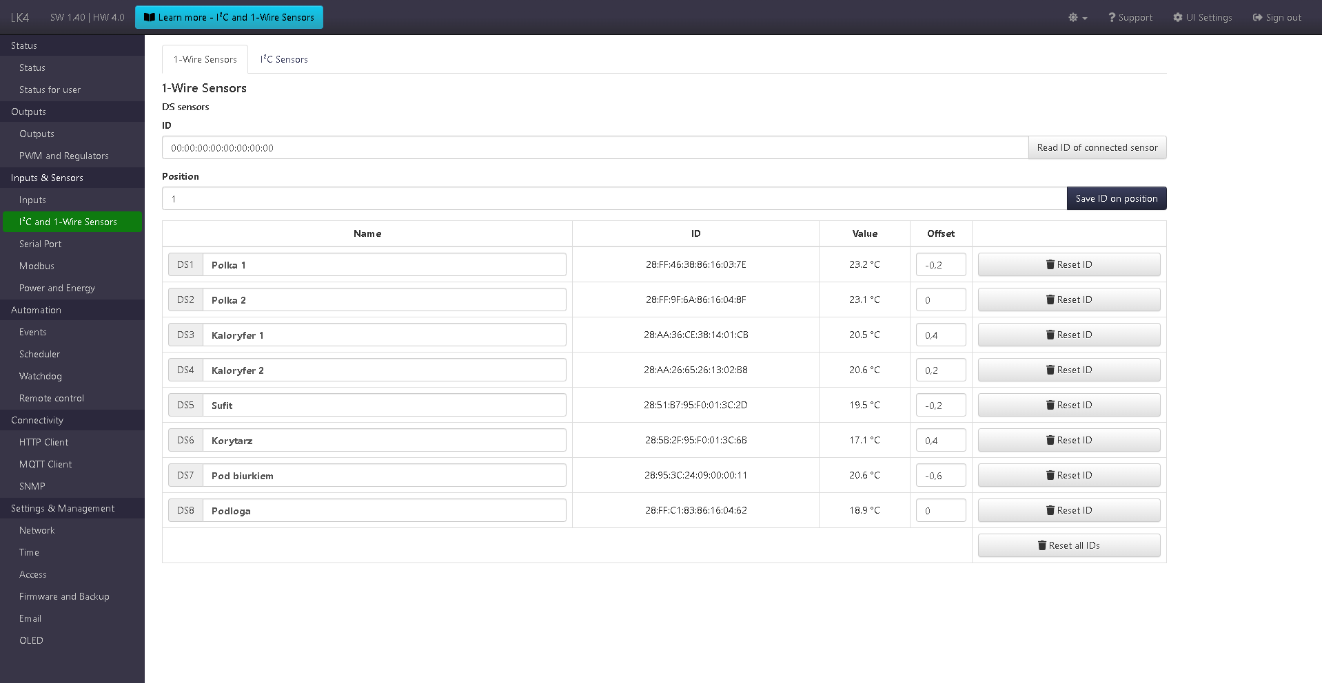
1-Wire (DS) sensor configuration section.
- A form with two fields: ID and Position. It allows reading the IDs of connected DS sensors and assigning them to positions in the table below. The value in the ID field can also be entered manually.
- A table with configured DS sensors. It contains a custom reading name, the assigned ID, the current reading, a field for setting an offset for the reading, and a reset ID button (removes the sensor from the given position). At the bottom of the table there is also a button to reset IDs for all positions.
I2C Tab
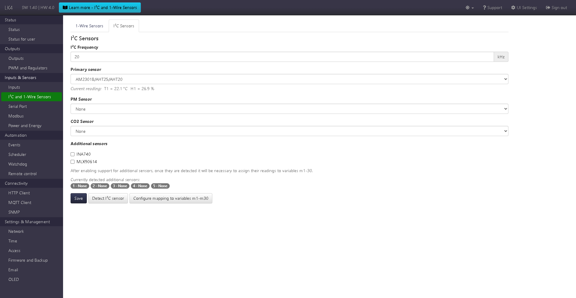
I2C sensor configuration section.
- A form allowing:
- setting the I2C bus frequency,
- selecting the primary I2C sensor (one of: None or BME280, AM2320, HTS221, BME680, AM2301B / AHT25 / AHT20),
- selecting the PM sensor (SPS30, APM10),
- selecting the CO₂ sensor (SCD40, ACD10),
- enabling support for additional sensors by selecting the appropriate options (e.g. INA740, MLX90614).
- A button for detecting sensors connected to the I2C bus.
After saving the configuration and performing sensor detection, the current readings of the detected sensors are displayed, confirming their presence and correct operation.
Additional I2C sensors are automatically assigned to five universal slots.
For each detected sensor, its readings are displayed, and further use requires assigning them to variables m1–m30 using the dedicated mapping configuration button.
Additional sensors (I2C)
Starting from version SW 1.24, the I2C sensor configuration section includes an Additional sensors subgroup, enabling support for extra sensors connected to the I2C bus, independent of the primary, PM, and CO₂ sensors.
Support for additional sensors has been expanded in subsequent software versions:
- INA740 – available since SW 1.24,
- MLX90614 – available since SW 1.38.
Enabling support for a given sensor type allows it to be automatically detected on the I2C bus after saving the configuration and using the sensor detection function.
Universal sensor slots
Additional sensors are assigned to five universal slots, labeled as positions 1–5.
- A maximum of 5 additional sensors can be supported simultaneously.
- Each detected sensor occupies one slot.
- Slots are assigned automatically after detecting sensors on the I2C bus.
Once a sensor is assigned to a slot, its position is permanently retained.
This means that after a device restart, the sensor will remain associated with the same slot.
The stable slot assignment is important for reading mapping and ensures predictable data presentation within the system.
Readings and parameters
For each slot, readings are displayed depending on the type of the assigned sensor.
One slot may provide up to 5 measurement parameters.
Example parameter sets:
- INA740
- voltage,
- current,
- power,
- energy,
- temperature.
- MLX90614
- object temperature,
- ambient temperature.
Readings are displayed in the Readings table, separately for each detected module.
Mapping to variables m1–m30
To use readings from additional I2C sensors in other device functions (such as Events, HTTP Client, MQTT Client, OLED, VOLED, or LTE Modem), they must be assigned to variables m1–m30.
Reading mapping to variables m1–m30 is performed using the button:
Configure mapping to variables m1–m30
A detailed description of mapping rules can be found in the documentation: Reading mapping.