Devices
Later in the documentation I will refer to Lan Controller v3, GSM Controller v3/v4.2 and other devices that can connect to our server via MQTT, simply as devices.
On this page you will find information on adding a new device to your account, configuring it, and editing its settings on the server side.
Devices page
The Device page is the central point of the mqtt.ats.pl website. On this page, you can view and manage all your devices, add new devices, or access graphs and tables with data from your devices.
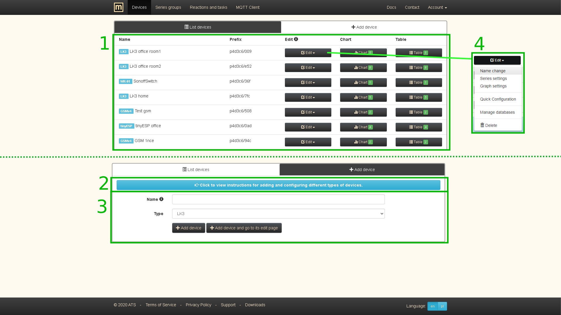
The picture below shows the Devices page with few devices. There are several important elements on it:
- List of devices assigned to the account. Contains names, types, prefixes, links to edit pages, chart and table views.
- Instructions for adding and configuring a new device (included in this documentation).
- Form for adding a new device. It is worth mentioning that Add a device and go to its edit page after adding a device, it will redirect you to the series settings page you need to visit to select the active series (for which you want to collect data).
- Links to editing pages where you can manage or delete the device.
Adding
The first step to start using the service is to add a new device to your account. The method of connection and configuration of supported devices to the MQTT server is presented below.
Server side steps for each device type:
- On the Devices page, complete the device adding form.
- Save with Add device button and wait for redirection and displaying information about success or possible error.
- Select the series you are interested in, in the Series settings in the Edit section of the Devices page.
LK3, LK4, tcPDU
There are two ways to configure MQTT client:
- Recommended Use Quick Configuration from the Edit section of the Devices page.
-
Enter the data manually in the form in the MQTT Client tab on LK3:
- Enable Mqtt - select it
- Enable authentication - select it
- Use TLS - deselect it
- Use LWT - currently does not matter
- Send by modem - select only if using GSM/LTE overlay
- Server address - mqtt.ats.pl - MQTT server host name (available on account info page)
- Port - 1883 - MQTT server port (available on account info page)
- Login - MQTT client username (available on account info page)
- Password - MQTT client password (available on account info page). Note it's not your account's password.
- Topic Prefix - Your device's prefix (visible next to the device on the Devices page)
- Sending period - 300 (unless otherwise stated on the website)
- KeepAlive - 300 (value equal to Sending period or slightly bigger)
- Sent periodically - Select at least one check box to send data
- Sent on change - currently does not matter (not available on tcPDU)
Confirm the changes with the Save button.
The device should then start sending data which can be observed in its Chart view. Generally, the first data should arrive within about 5 minutes of setting up the device.
Configuration troubleshooting
If you have configured your device and waited for at least 5 mins for data in Chart view and didn't see any messages coming in then something is wrong. To learn what could have gone wrong and how to fix it keep reading.
First start with few checks:
- Is there MQTT connected message at the top of MQTT client tab (on device's page)? If there isn't any status message then it's strongly recommended to upgrade firmware to newer version to have this feature.
- Yes - The problem is in MQTT Client configuration on device.
- No - The problem is in Network configuration or MQTT Client configuration on device.
- Can device fetch time via NTP (Time tab on device) with default settings (pool.ntp.org:123)?
- Yes - The problem is in MQTT Client configuration on device.
- No - The problem is in Network configuration on device.
Solutions:
- Network configuration - For static configuration make sure to enter valid IP address, gateway and DNS (8.8.8.8 can be used as primary DNS). If you are not sure of those values then use DHCP, but remember that you will have to find your device's new IP address to access it (leases in DHCP Server section in most routers).
- MQTT Client configuration - The easiest and the fastest solution is using Quick Configuration, mentioned in Adding section. If for some reason you can't use it, then carefully go through manual configuration procedure described at the beginning of this section. Make sure there is no extra trailing spaces in any of the fields (especially Password and Prefix).
The above issues are the most common ones, but there might be problems caused by external factors, e.g. restrictive firewall blocking outgoing data.
GSMv4.2
-
Insert the SIM card into the GSM Controller, connect the power supply. After a while the green LED should blink 3 times per second.
Attention!
The default APN settings of the GSM Controller are "internet","","" (username and password not set). If your operator's settings are different, you must change them on the Controller by sending an SMS to its number with the following content (with inserted data for your operator):
1234:gprsapn="APN_NAME","USERNAME","PASSWORD"Attention!
If the green diode flashes once per second, the device is not connected to the network - check the validity of the card.
-
Go back to the Devices page on mqtt.ats.pl, select GSM pairing in the Edit section for the added device.
- Find the GSM ID number on the sticker on the short instruction (under the barcode) attached to the device, then enter it in the field on the page and press Pair GSM Controller with the server.
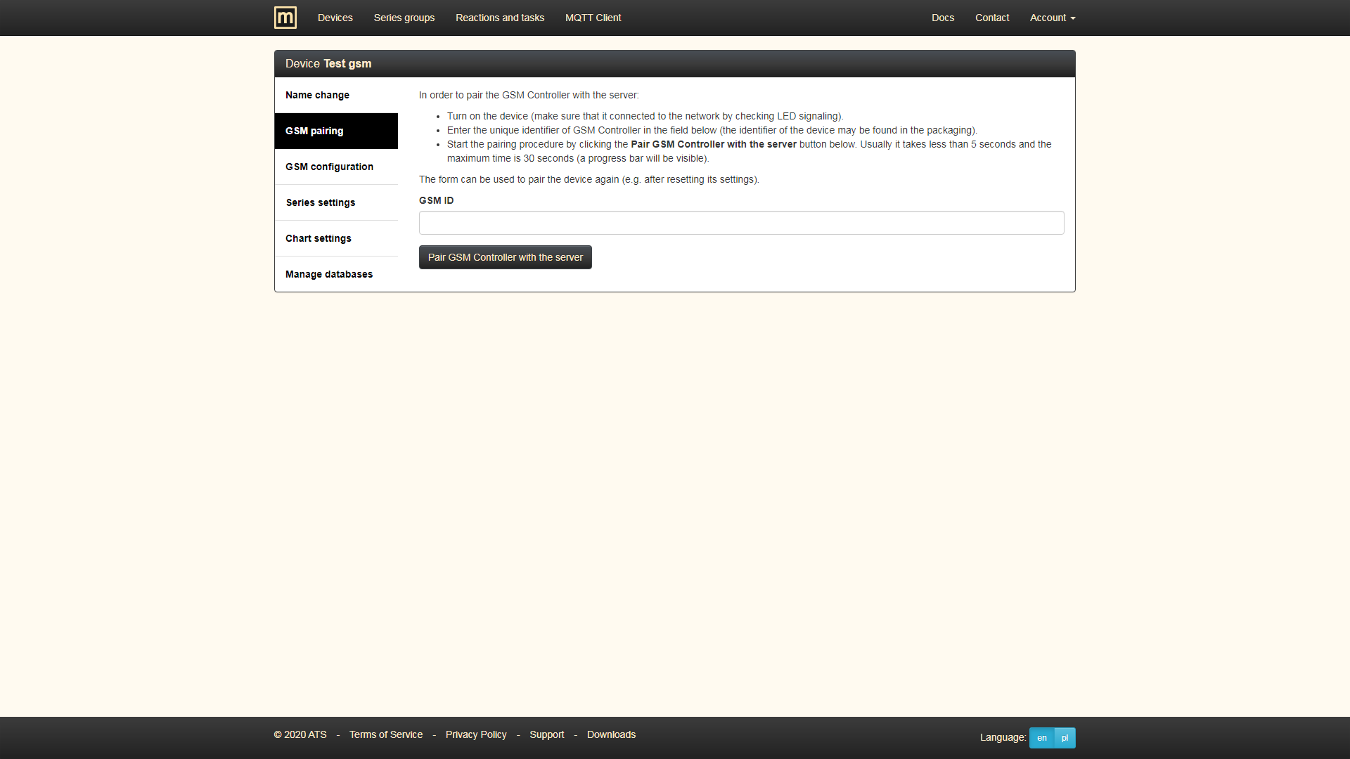
- The GSM Controller should receive the configuration from the server and restart. The procedure on the website should take about 5 seconds (with a limit of 30 seconds) and the restart of device about 40 seconds.
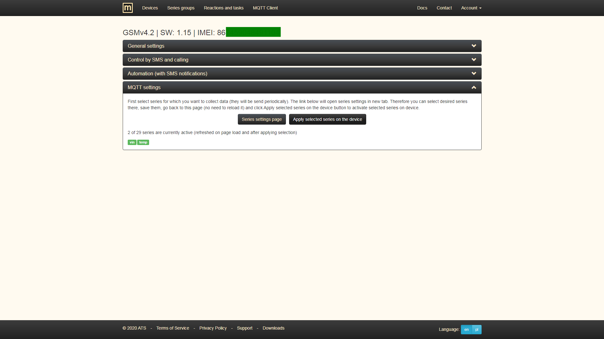
- Go to the GSM Configuration page (under the Edit button) to further configure the device. It is important that in the MQTT Settings section, after selecting the series, save the changes on the device by clicking Apply selected series on the device.
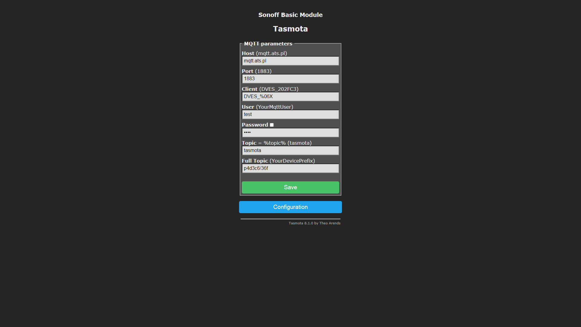
WR-01, Tiny Smart Relay (Tasmota)
-
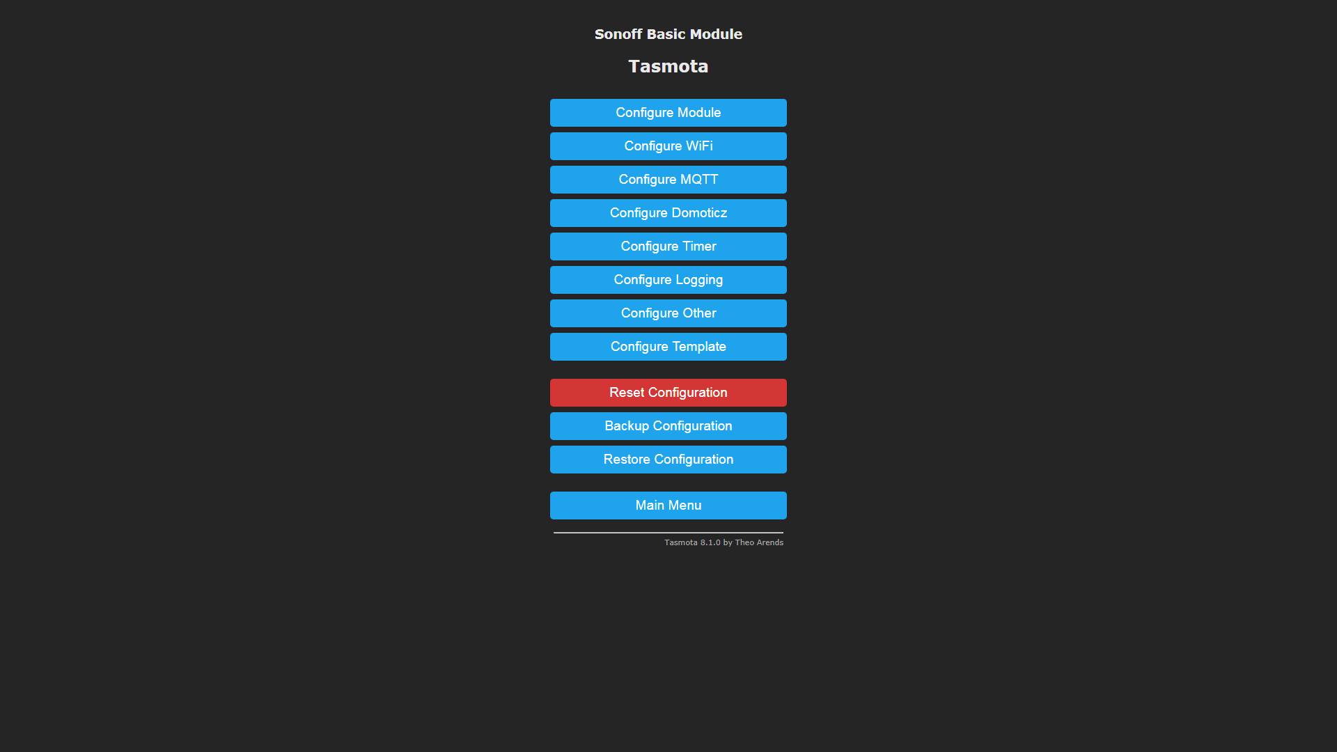
Open the Tasmota device page.
-
In the Configure MQTT section, enter:
- Host: mqtt.ats.pl
- Port: 1883
- User: MQTT client username (available on Account info page)
- Password: MQTT client password (available on Account info page)
- Full Topic: Your device's prefix (visible next to the device on the Devices page)
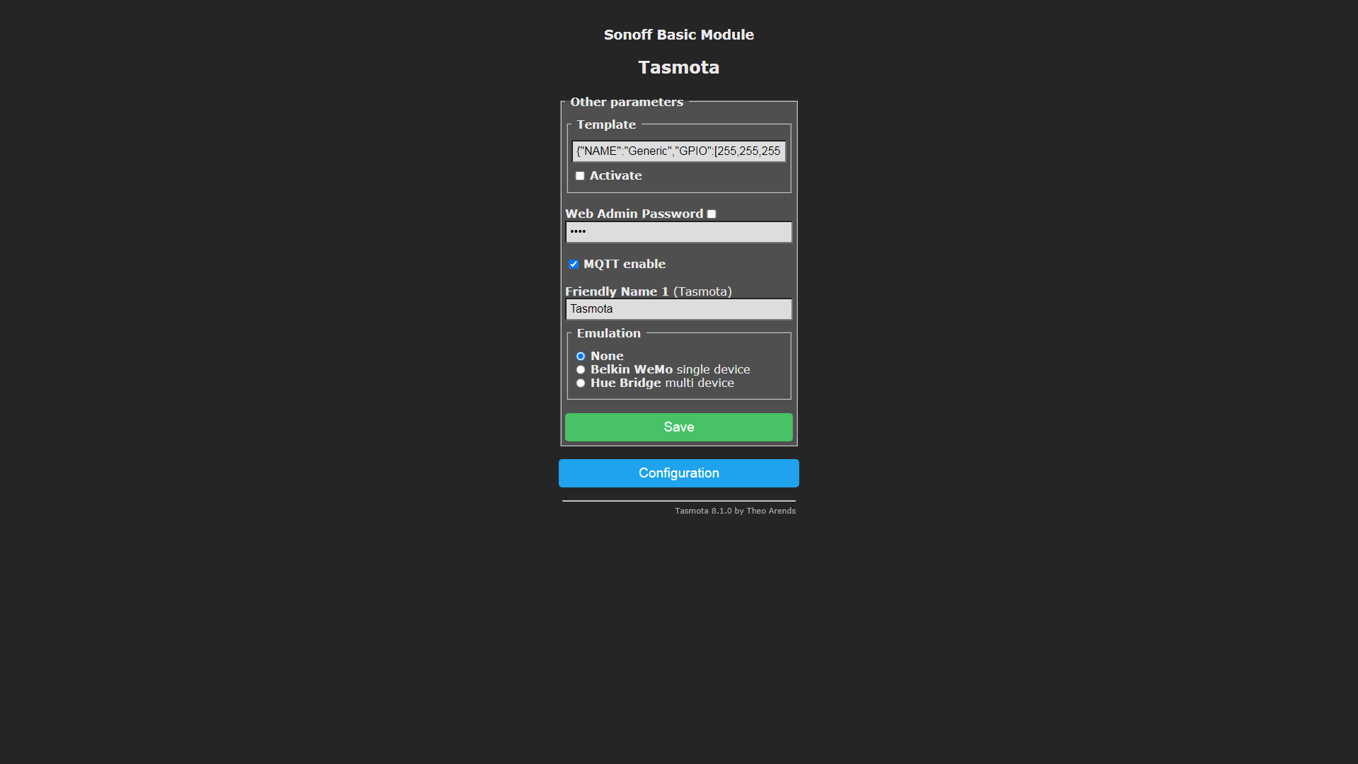
-
Make sure MQTT enable is checked in the Configure Other section.
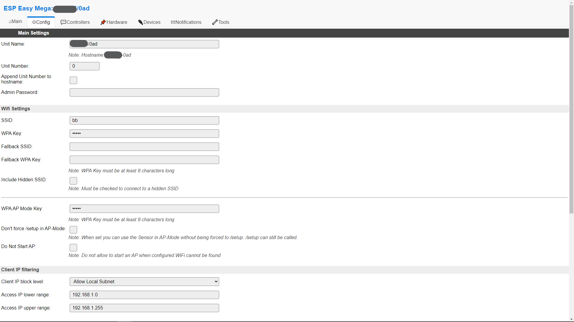
tinyESP
Manual prepared for ESP Easy firmware, version ESP_Easy_mega_20220427_normal_IRext_no_rx_ESP8266_4M2M.
-
After initial setup (WiFi, access settings, etc.). In ESP Easy, go to the Config tab and in the Unit Name field, enter the device prefix generated on mqtt.ats.pl (visible next to the device on the Devices page). This value will be used as host name, MQTT client ID, and part of MQTT topics.
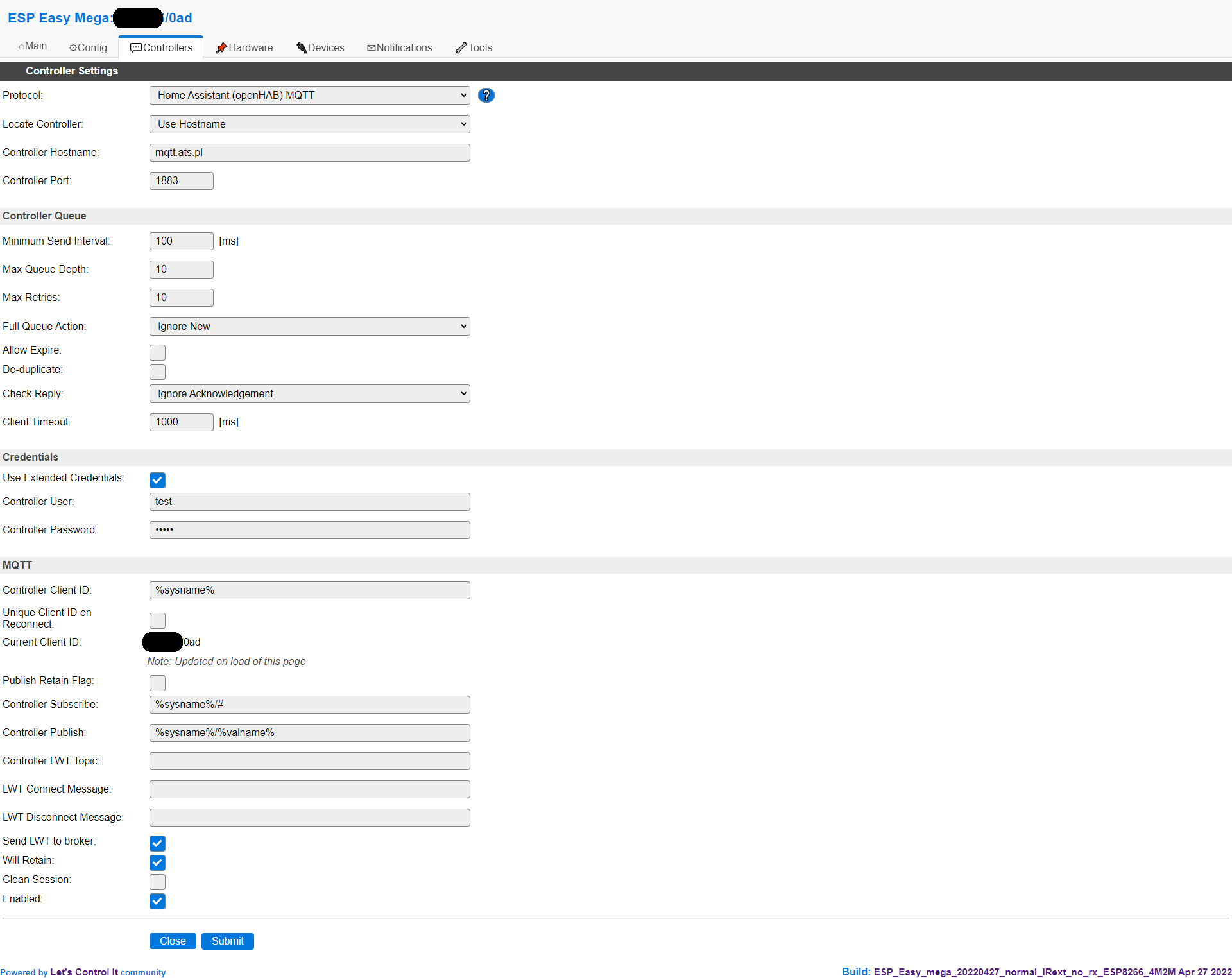
-
In the Controllers tab, click Add next to the first item, select Home Assistant (openHAB) MQTT and fill in the form:
- Locate Controller: Use Hostname
- Controller Hostname: mqtt.ats.pl
- Controller Port: 1883
- Client Timeout: 1000
- Use Extended Credentials: select
- Controller User: MQTT client username (available on account info page)
- Controller Password: MQTT client password (available on account info page)
- Controller Client ID: enter
%sysname% - Controller Subscribe: enter
%sysname%/# - Controller Publish: enter
%sysname%/%valname% - Enabled: select
Optionally, you can also select Send LWT to broker and Will Retain.
-
Then configure the connected sensors/modules in the Devices tab.
-
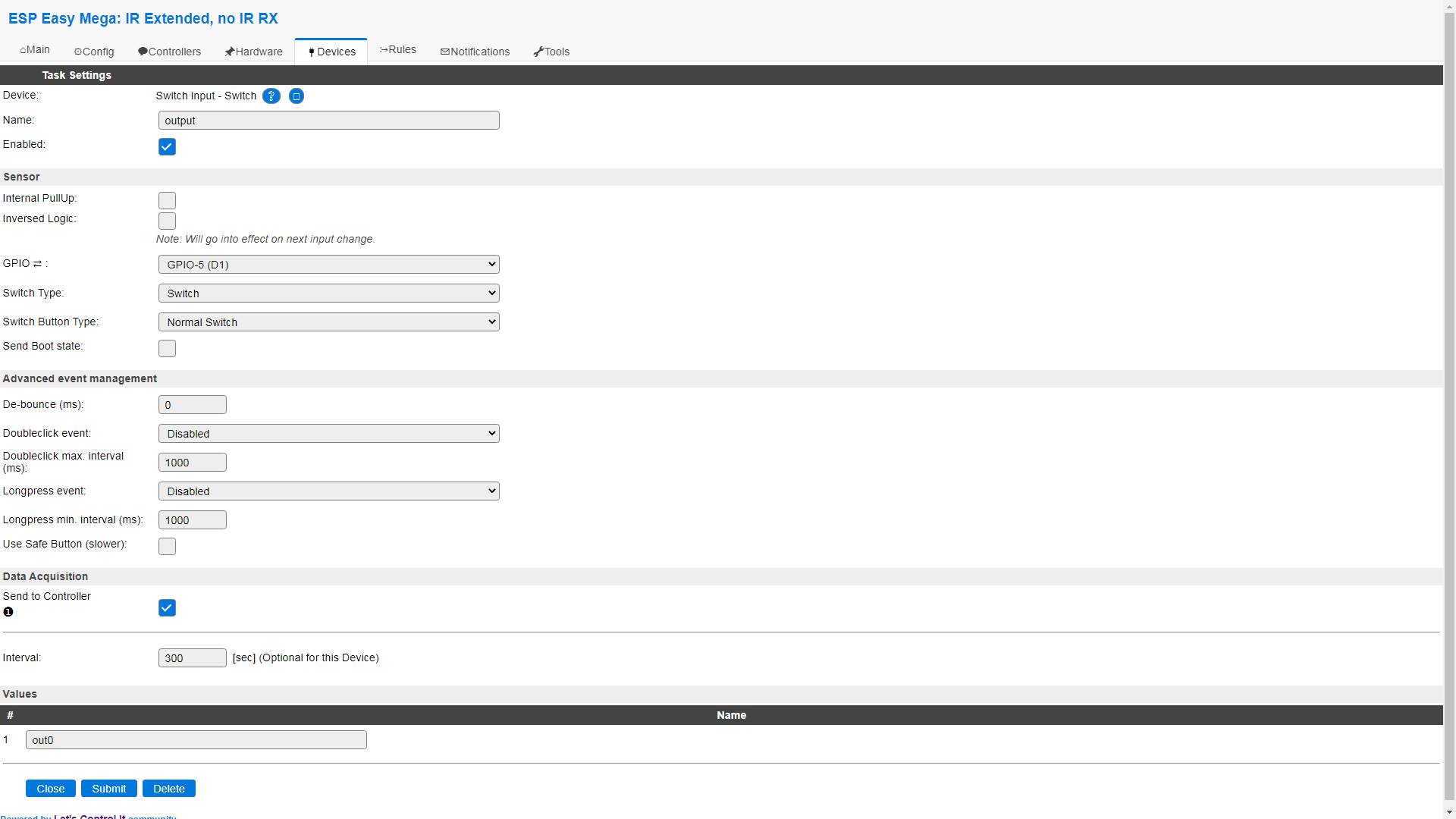
Relay out0 - add Switch input - Switch changing only:
- Name: output
- Enabled: select
- GPIO: GPIO-5 (D1)
- Send To Controller: select next to the first item (MQTT controller set in step 2)
- Interval: 300
- Values: 1 - out0
-
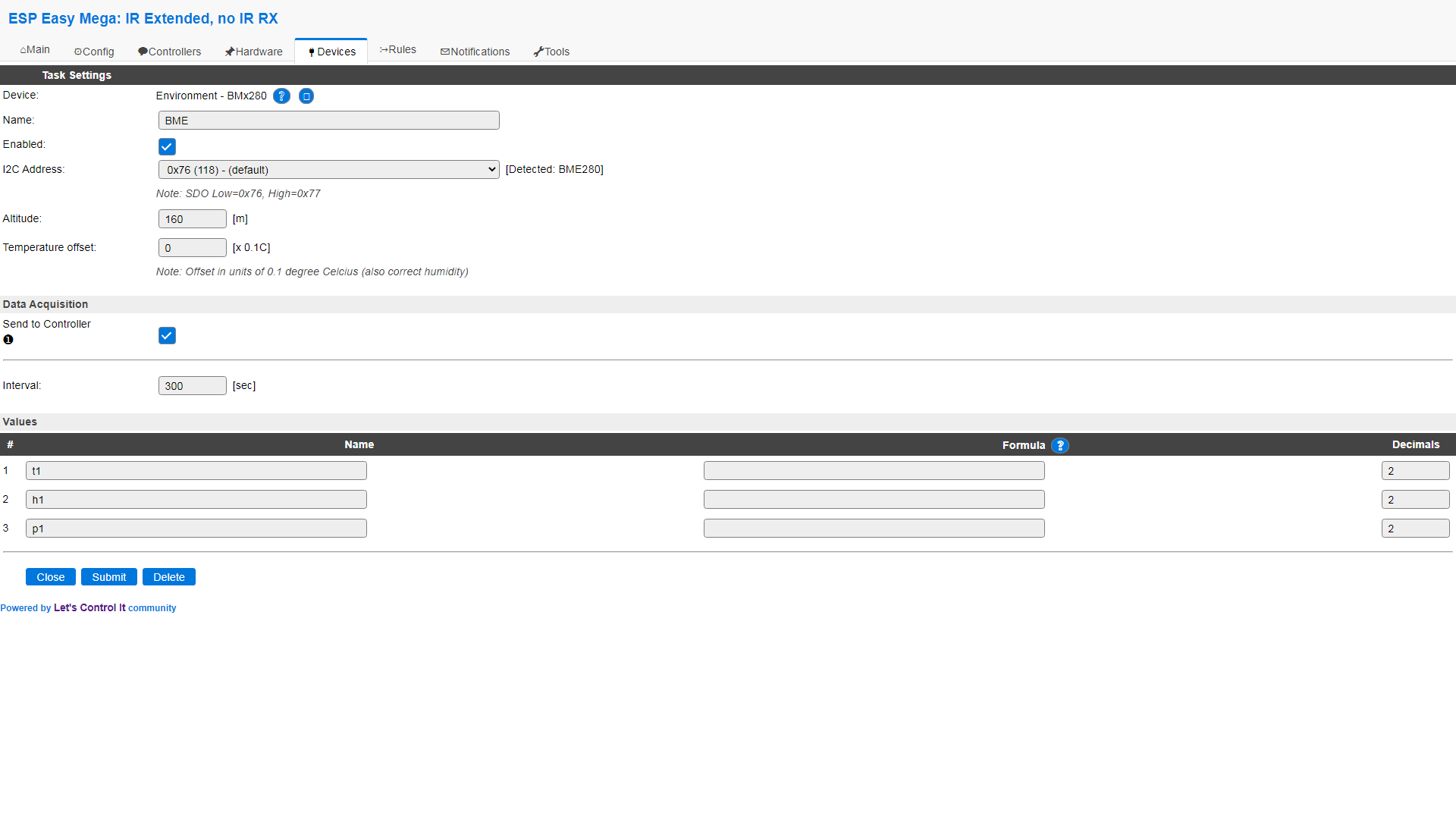
BME280 sensor (temperature, humidity and pressure) - add Environment - BMx280:
- Name: bme
- Enabled: select
- I2C Address: likely 0x76 (118) - (default)
- Send To Controller: select next to the first item
- Interval: 300
- Values: 1 - t1, 2 - h1, 3 - p1
Optionally, you can set Altitude and Temperature offset as desired.
-
With other sensors, remember that the value entered in the Values section has to correspond to the topics of the available series on the mqtt.ats.pl website Series settings, e.g. ds1, custom1, etc.
-
Configuration
After adding a device to your account you will be able to configure some options for it (mentioned in Devices page section). Below is short description of available settings and device related management functions, available in Edit section.
Name change
In this section you can change the name of the device. It may be a good idea to use descriptive names to easily distinguish your devices. The name can be up to 100 characters long, including letters, numbers, spaces, and periods.
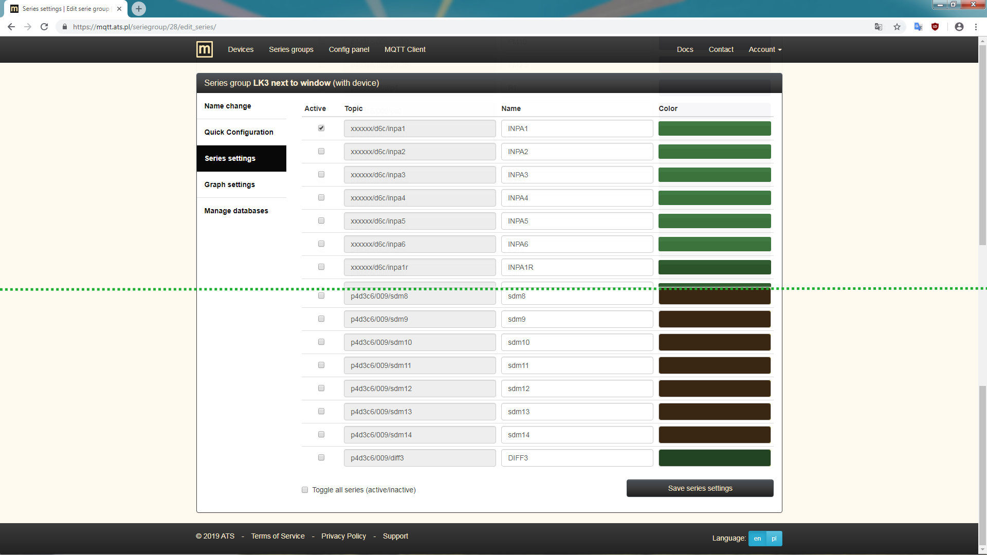
Series settings
Here you select the active series that should be available in the chart and table views. Besides, you can also set the series names and their color on the chart.
When a series is activated for the first time, there is extra step that configures the collection of data for it, received over MQTT, for use in chart and table views.
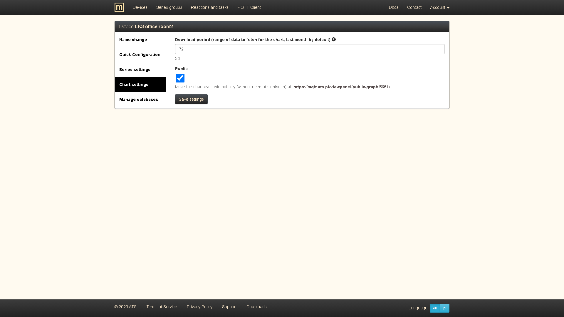
Chart settings
They allow you to select the range of data to be downloaded that will be presented on the chart. The selected range is always counted until the graph is displayed, e.g. with a selected range of 7 days, the data for the last 7 days in the past, from the moment of visiting the graph view, will be displayed. It defaults to the last month (more specifically the last 30 days). It should be remembered that with the greater number of series and the wider range of data, the time needed to prepare the chart for displaying also increases.
You can also choose whether a given chart should be publicly available, i.e. without logging in, at the address provided on the website.
Quick Configuration (for LK3, LK4, tcPDU)
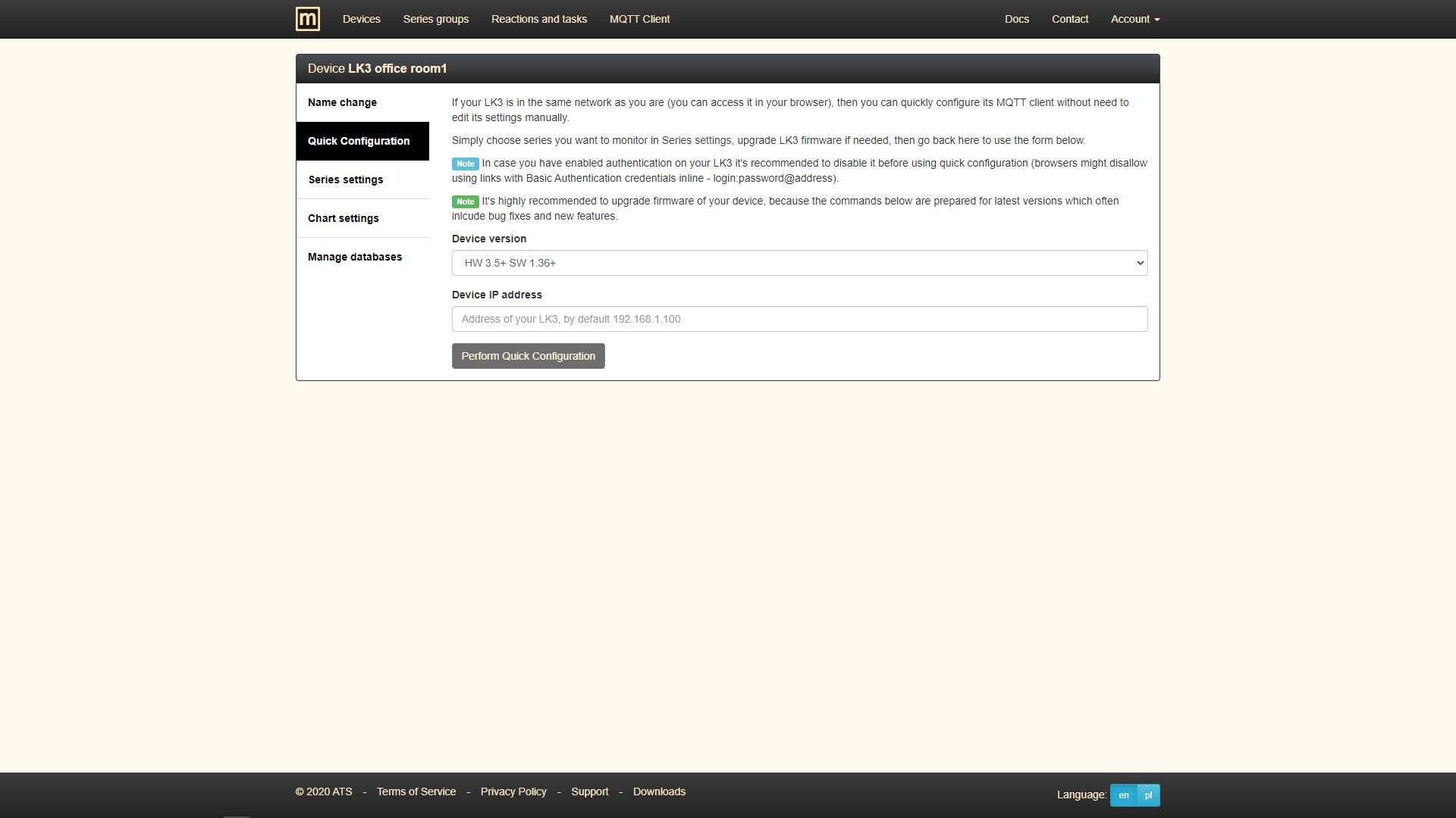
A function that facilitates the configuration of LK3, LK4 and tcPDU for cooperation with the server. It is recommended over manually configuring the MQTT Client on the device as it is faster and avoids common errors such as typos or entering an invalid value. It consists in generating the MQTT client configuration for the device, in accordance with the settings on the server (active series, MQTT client data).
To use it:
- Make sure that the device is using a supported firmware version (according to the options available in the Device version field in the Quick Setup form). Firmware update instructions are available in documentations of LK3, LK4, tcPDU.
- Make sure that the device page is reachable in the browser.
- Select as active the series you want to monitor in Series Settings.
- Use the Quick Configuration form, selecting the appropriate device version (HW and SW) and entering the IP address of the device and clicking the Perform Quick Configuration button (optionally by copying the link address under the button and pasting it in a new tab in the browser).
- As a result, on the MQTT Client page on the device you should see the message MQTT CONNECTED on a green background. Otherwise, see the instructions in Configuration troubleshooting.
GSM pairing (for GSMv4.2)
Function for connecting GSM Controller v4.2 to the server. It consists in sending the MQTT connection configuration to GSMv4.2, which by default connects to the configuration server. The use of the GSM pairing is presented in the first 4 steps of the adding a device manual.
GSM configuration (for GSMv4.2)
A function that allows you to configure GSM Controller v4.2 settings, such as automation (similar to Events on LK), selection of trusted numbers, selection of sensors, selection of active series to send their data via MQTT to the server.
GSMv4.2 configuration can also be done using the serial port or SMS messages (the function on the website uses the MQTT connection).
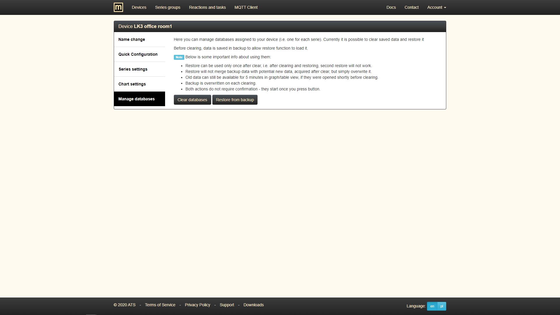
Data management
Currently, it is limited to deleting the collected data for a given device. It can be useful when the device is used to measure another location, so that the data only applies to the new location.
Deletion
This is not exactly a configuration, but it occurs in the interface alongside other functions available for the device. It simply allows you to remove a device from your account, e.g. when you want to add a different type of device but you don't have any free spaces.
Controlling
You can control your devices remotely as long as they are connected to our MQTT server.
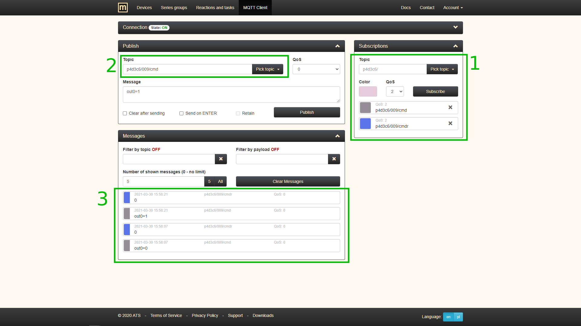
Following example/instruction shows how to send commands to your device (here to LK3), using MQTT Client page.
- Subscribe to
/cmdand/cmdrtopics for your device (its prefix +/cmd). Topic/cmdis the one to which commands should be send and/cmdris the one to which LK3 sends confirmation that it processed command. - Choose topic
/cmdin the Publish section (the same one from previous step). Type a command into Message field, eg.out0=0orout0=1, and send it with the Publish button. - In result, messages you have sent to topic
/cmdand responses from/cmdrshould appear in Messages section.
MQTT commands
Devices supported by our server have different commands available and minor differences in the topics on which they should be sent.
-
LK3 commands are described in LK3 documentation.
-
The commands for GSMv4.2 are described in GSMv4.2 documentation.
-
For WR-01 (Sonoff-Basic module) full command descriptions are available in Tasmota software documentation. In our case, the following information is sufficient:
- command's topic - ends with
/cmnd/power - command's result topic - ends with
/RESULT - commands:
- turn output on -
1,on,ON - turn output off -
0,off,OFF - toggle output -
2,toggle,TOGGLE
- turn output on -
- command's topic - ends with