Controlling smart WiFi plug from Lan Controller
Requirements
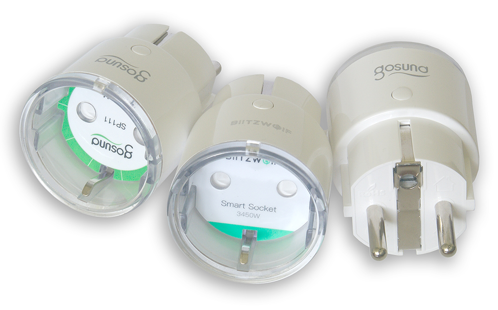
- Smart plug (based on ESP8266, using Tuya firmware, eg Gosund SP111) with Tasmota firmware loaded.
- Lan Controller v3.5+.
Instruction
-
On the HTTP Client page, enter in the field Server address 2 the text
<PLUG IP ADDRESS>:80/cm?cmnd=Power %44, where in place%44the output state out1 will be inserted, according to description under the form.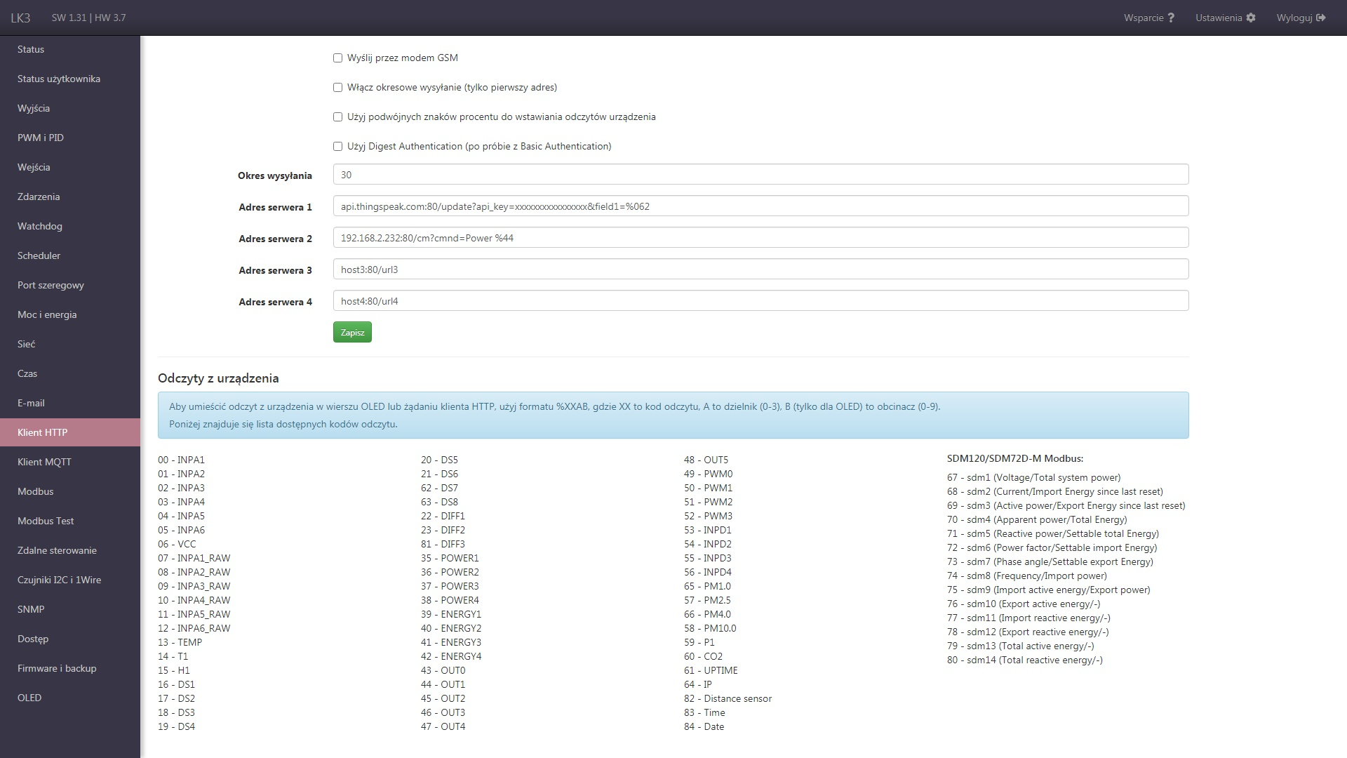
-
On the Events page, add the event
OUT1 = 1 => http2and enable it.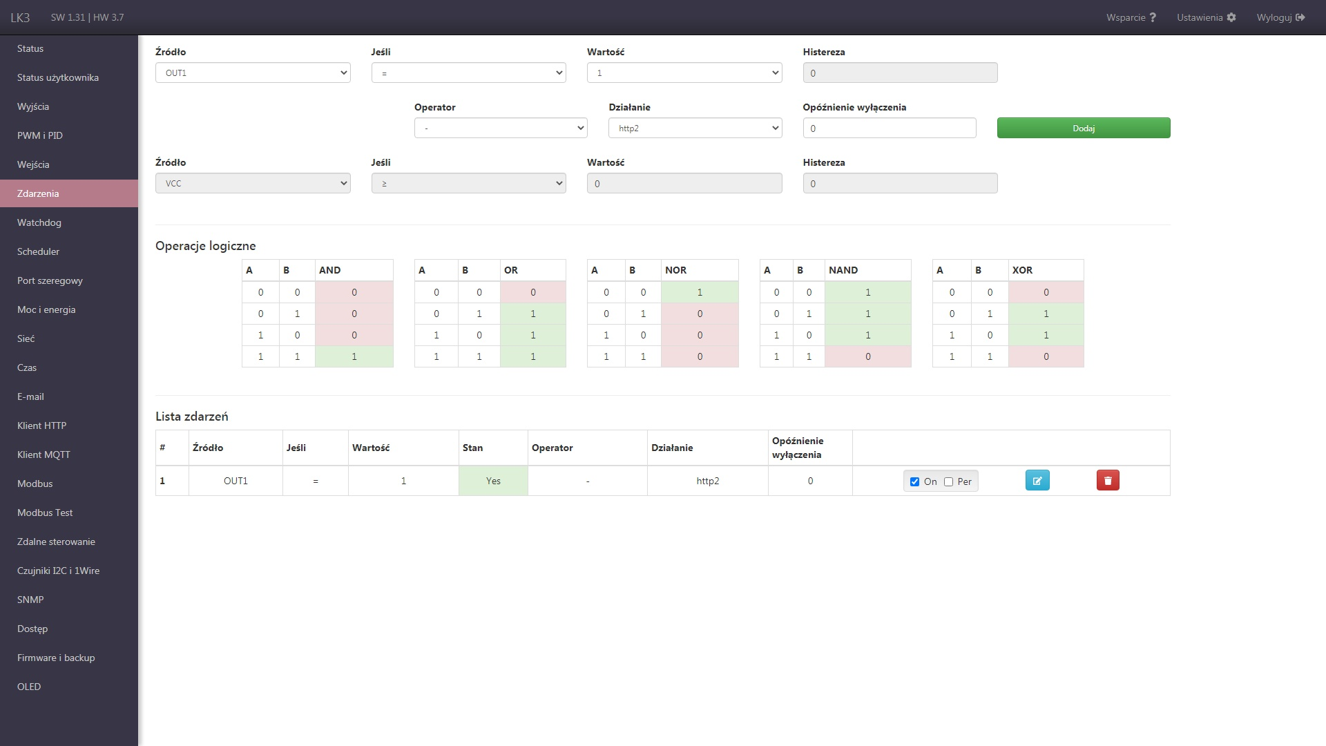
In result, the output state out1 corresponds to the state of the plug - when the LK output state changes, the plug state will also be changed using the HTTP command.
You can use another field Server address and another output out, or you can link the state of the plug with another value from LK, e.g. with a temperature reading.
Preparation of the plug with Tasmota firmware
If the plug does not have Tasmota firmware installed, you will additionally need:
- Linux computer with a WiFi adapter (e.g. Raspberry Pi 3B/3B+/4B).
- WiFi device (e.g. smartphone).
The presented manual includes a description for Raspberry Pi 4B, Android smartphone, Gosund SP111 plug and Lan Controller v3.5+ (HW 3.7). Therefore, some steps may differ slightly when using other components.
Preparing a Linux computer
- Prepare an SD card with the system.
- Download the program for uploading the system image to the SD card, eg. balenaEtcher or Raspberry Pi Imager.
- Download a system image, eg. Raspberry Pi OS Lite from raspberrypi.org.
- After uploading the image, you can add a file called
ssh(without extension) on the boot partition in order to start the SSH server.
-
Prepare the Raspberry Pi software.
- Start the Raspberry Pi with the prepared card and Ethernet connection to the Internet.
- Connect to Raspberry Pi via ssh, default login is pi:raspbery.
-
Enter the command
sudo raspi-config, go to the Advanced Options section and select Expand Filesystem. Upon exiting raspi-config, you should be prompted to reboot, which should be performed.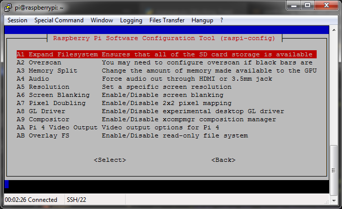
-
Update the system and install the necessary packages by typing the following commands in the console (may require confirmation after each):
sudo apt-get update
sudo apt-get dist-upgrade
sudo apt-get install network-manager
sudo apt-get install git
Installation and use of tuya-convert
-
Install the tuya-convert application to upload other firmware to the plug.
git clone https://github.com/ct-Open-Source/tuya-convert cd tuya-convert ./install_prereq.sh -
(Optional) Download a newer Tasmota firmware (np.v8.5.1 tasmota-lite.bin).
cd files wget https://github.com/arendst/Tasmota/releases/download/v8.5.1/tasmota-lite.bin mv tasmota.bin tasmota-included.bin mv tasmota-lite.bin tasmota.bin cd .. -
Launch the application and follow its instructions to upload new software.
./start_flash.shFirst you need to accept with
yes+enter. Later, there may be questions about freeing ports (eg 53 occupied by dnsmasq) to which you should answery.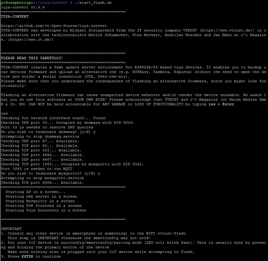
Then turn on the plug and connect the smartphone to the network indicated in the manual (in this case vtrust-flash). Confirm with
enter, after a while select firmware Tasmota (in this case 3 tasmota.bin).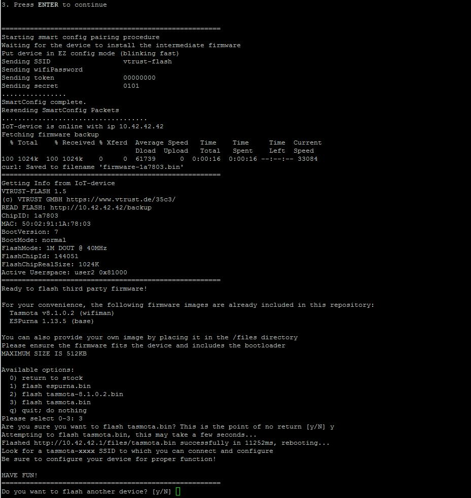
Plug configuration with Tasmota firmware
- Connect to the tasmota_XXXX network, visit the address 192.168.4.1 in the browser, complete the WiFi connection form.
-
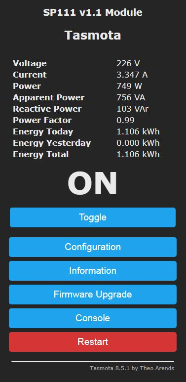
Find the device address in the indicated WiFi network and visit it in the browser.
-
(Optional) The device can also be connected to the mqtt.ats.pl server as WR-01, so that it can be controlled from the ATS MQTT Client application. Information on how to link device with mqtt.ats.pl service can be found here.
Info
We no longer provide a modified version of the Tasmota firmware as we have added support for the standard version on the server side. In case of problems with connecting the device and/or collecting data, please contact me via the contact form at mqtt.ats.pl.
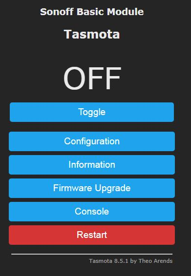
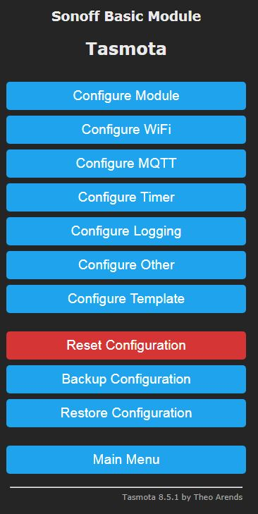
-
Go to the Configuration section and then Configure Other.
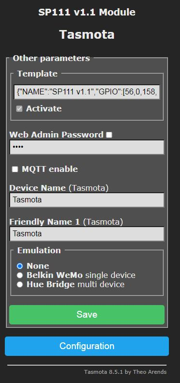
-
Enter text below into Template field (first option is with red LED when plug is on, second option is blue LED) and select Activate:
{"NAME":"SP111 v1.1","GPIO":[56,0,158,0,132,134,0,0,131,17,0,21,0],"FLAG":0,"BASE":45}{"NAME":"SP111 v1.1","GPIO":[158,0,56,0,132,134,0,0,131,17,0,21,0],"FLAG":0,"BASE":45}You can find templates for other devices here.
-
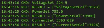
For more accurate energy consumption measurements calibration is required.
Calibration consists in setting the three parameters CurrentCal, PowerCal and VolatageCal, and is precisely described here.