Status
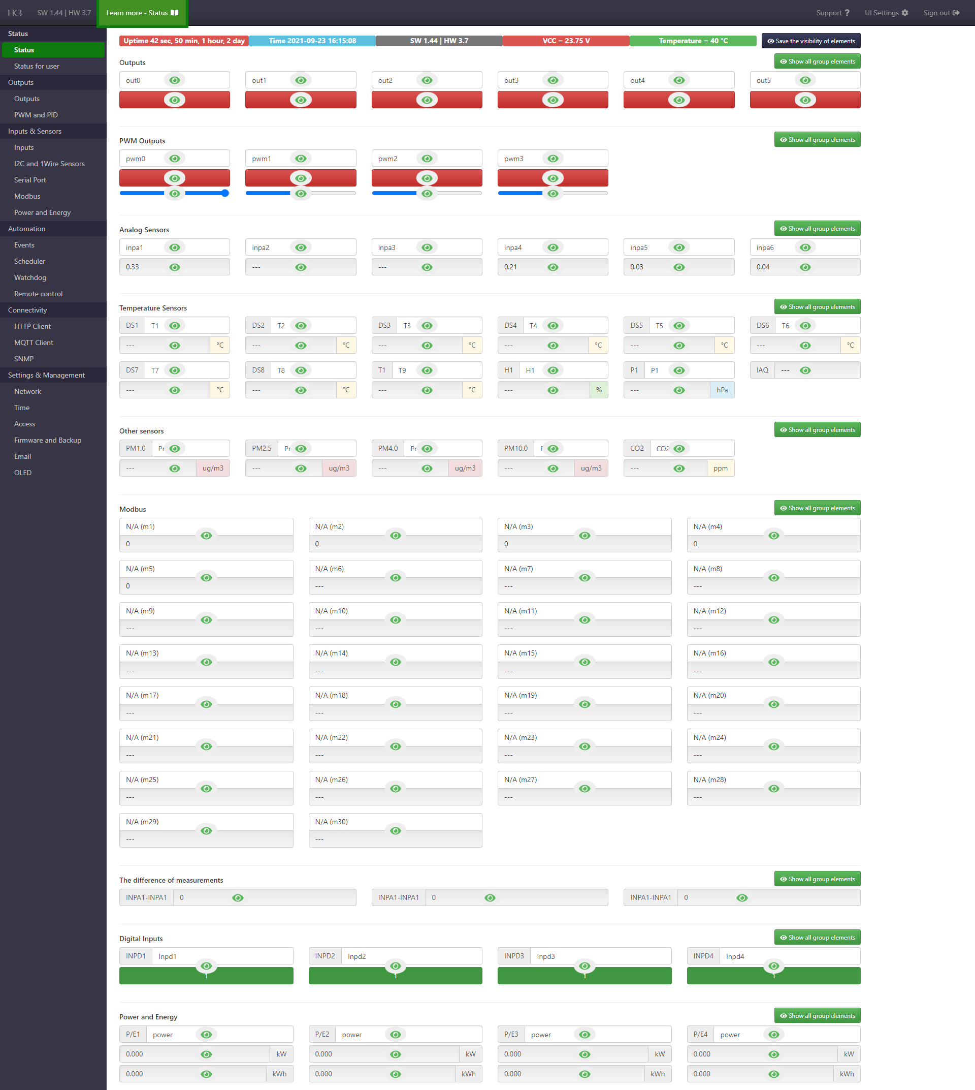
Page presenting data read from the device, such as the state of outputs, PWM outputs, analog inputs, digital inputs, sensor readings and proper names for all of the listed fields.
Page elements
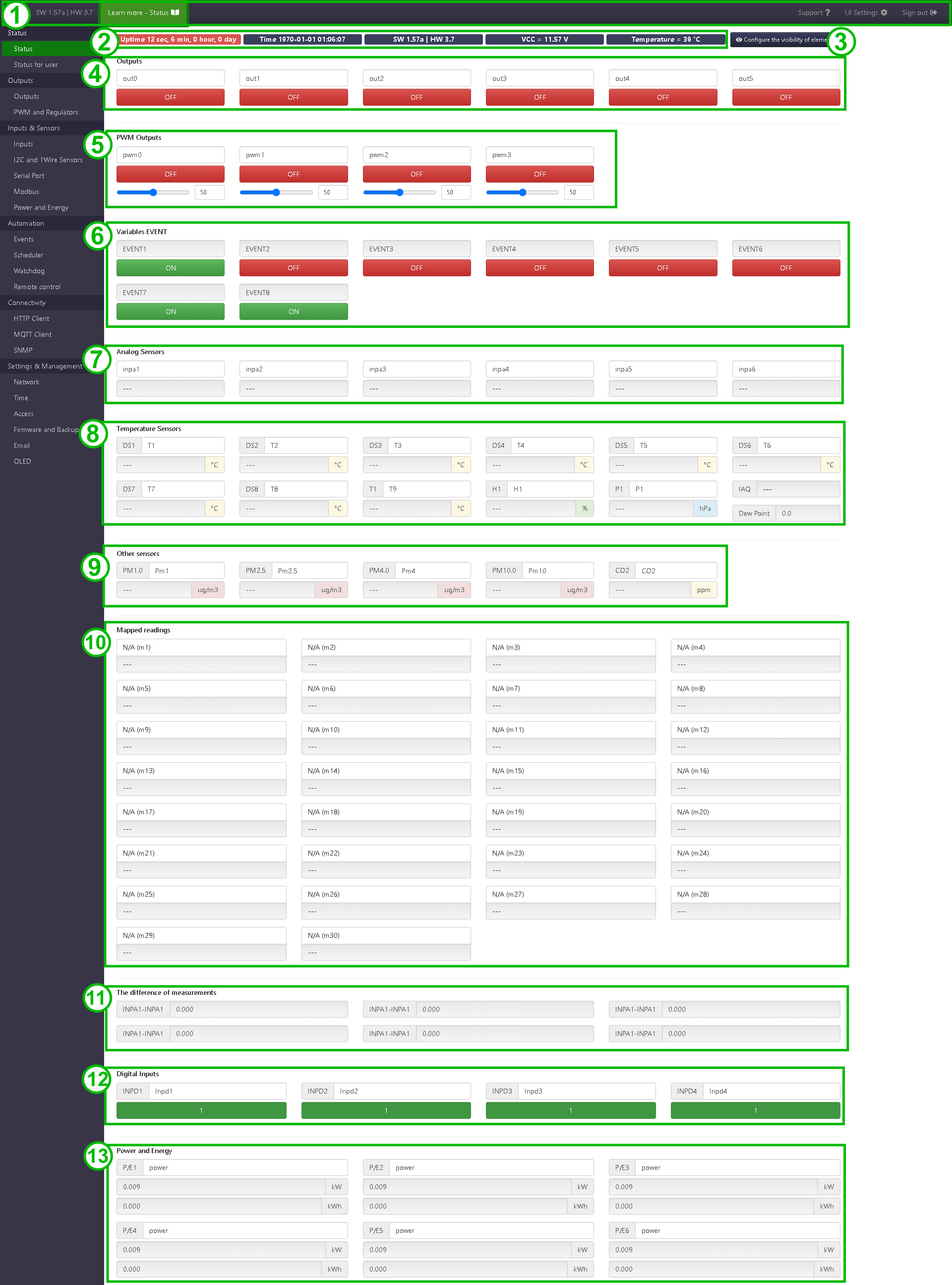
- Top navigation bar, visible on every page after logging in. On the left, it contains information about the firmware and hardware versions, a green padlock for https connection, and a link to the documentation page for the currently displayed page. On the right there is a link to UI settings, help materials and a logout button.
-
Information panel.
- time since the last restart (Uptime)
- date and time of the device
- firmware and hardware version
- power supply voltage
- processor temperature
Option confirmation that the device was on or after restart
After turning on the LC3 or its restart, the Uptime field has a red background. If you click on this field, it will change to orange and remain like that until the device is restarted.
Thanks to this you can check whether in the meantime the device has been restarted or lost power, without having to remember the value of Uptime - just check on the website if the highlight color has changed.
-
Button to activate the edit mode of the visibility of elements and to save the visibility settings.
-
Outputs ON/OFF.
It contains a field with an editable name and a state change button that also shows the current state.
From version HW 3.5+ SW 1.57 on the buttons there is also information whether the periodic switching is active - the inscription AUTO will appear.
-
PWM outputs.
It contains a field with an editable name, a state change button, and a slider to change the fill factor.
-
Buttons for setting the state of special EVENT variables.
-
Analog sensors.
It contains a field with an editable name and a converted value from the selected sensor (eg current value in A).
-
Temperature (DS18B20), humidity (AM2320) and pressure (BME280/HTS221) measurements.
It contains a field with an editable name and a field with a reading.
Selection of active sensors in the I2C and 1-Wire sensors tab.
-
Other measurements (CO2 and PM).
It contains a field with an editable name and a field with a reading.
Selection of active CO2 sensor MH-Z16/19, PM SDS011, PM SPS30 in the tab Serial port. In the case of SPS30 it is possible to connect via I2C - configuration in I2C and 1-Wire sensors.
-
Mapped readings (Modbus or custom 1-Wire measurements) - fields with name, value and unit.
-
Differential measurements.
Displays the difference, sum, quotient or product of two selected measurements (e.g. temperature, power, energy). Configurable in the Inputs tab.
-
Digital inputs.
It contains a field with an editable name and a field with a logical state.
-
Power and energy readings.
It contains a field with an editable name and fields with power and energy readings.
Editable names
Name of input, output or reading, must have from 1 to 15 characters, excluding characters: %, &, *, #, ".
Visibility of elements
The user can choose which fields should be visible on the Status and Status for user pages. To do this, click the button Configure the visibility of elements in the upper right part of the page (in versions before HW 3.5+ SW 1.44 it was split between pages Inputs, PWM and PID, Outputs and Power and energy).