Modbus
Modbus Sensor RTU (RS485)
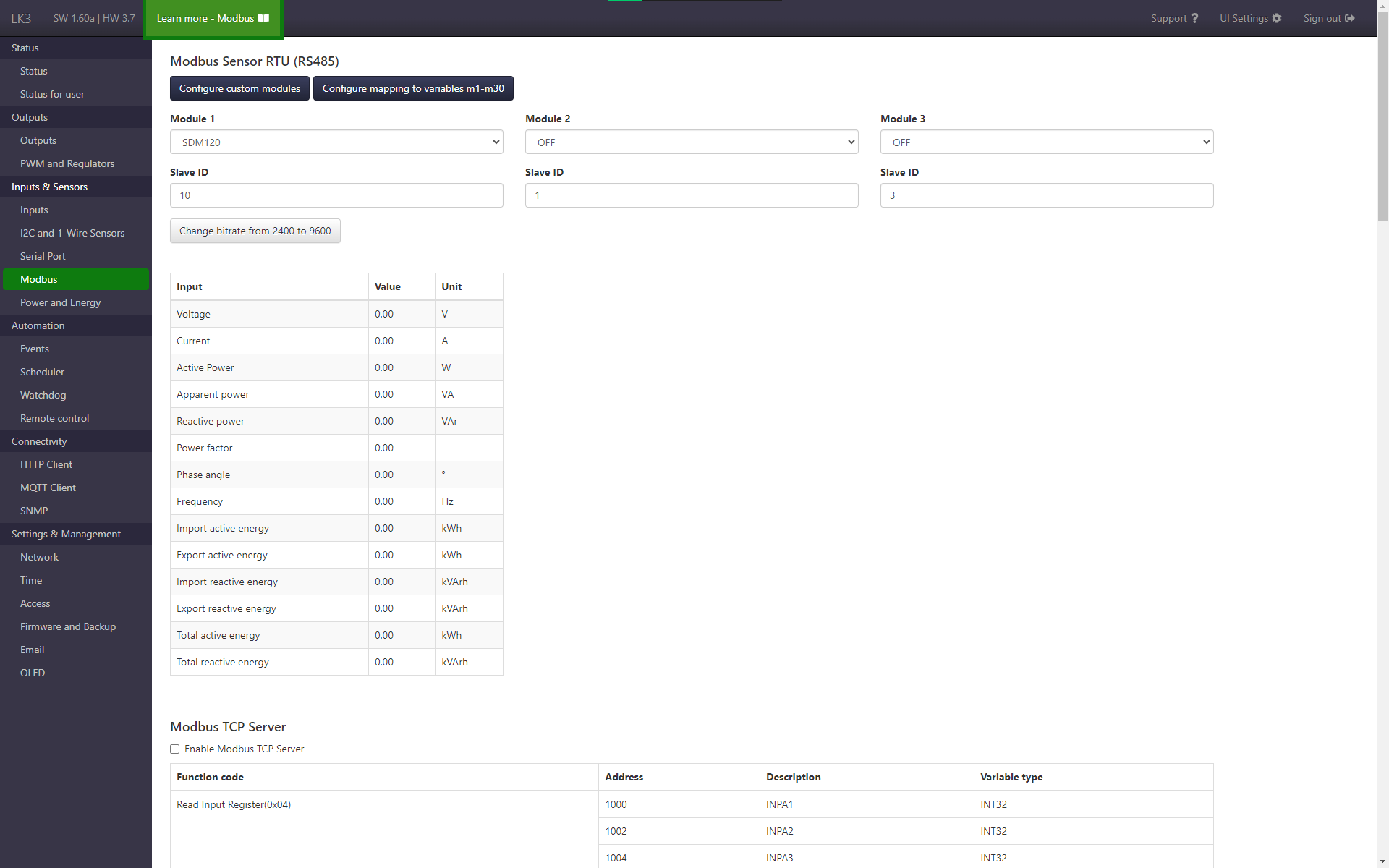
Since version HW 3.5+ SW 1.36 it is possible to operate up to three independent devices on one Modbus bus. The configuration, as before, consists in selecting the module and specifying its slave ID, with the difference that up to three slots can be supplemented this way.
Following modules are supported:
- SDM120
- SDM72D-M
- RDO-PRO X
- Epever Tracer
- Sofarsolar
- GTIL
- Danfos EKC 202C
- SDM630/72D-v2 (since HW 3.5+ SW 1.57)
- CHINT-DTSU666 (since HW 3.5+ SW 1.57)
In addition, it is possible to add support for other Modbus devices using the adding own/custom modules feature.
Using Serial Port and Modbus features
In versions HW 3.5 and HW 3.6, you can only select one module from the Serial Port or Modbus card.
From version HW 3.7 onwards, two separate serial port interfaces are available on the board, which allows the use of both functions: Serial port and Modbus at the same time.
Custom devices
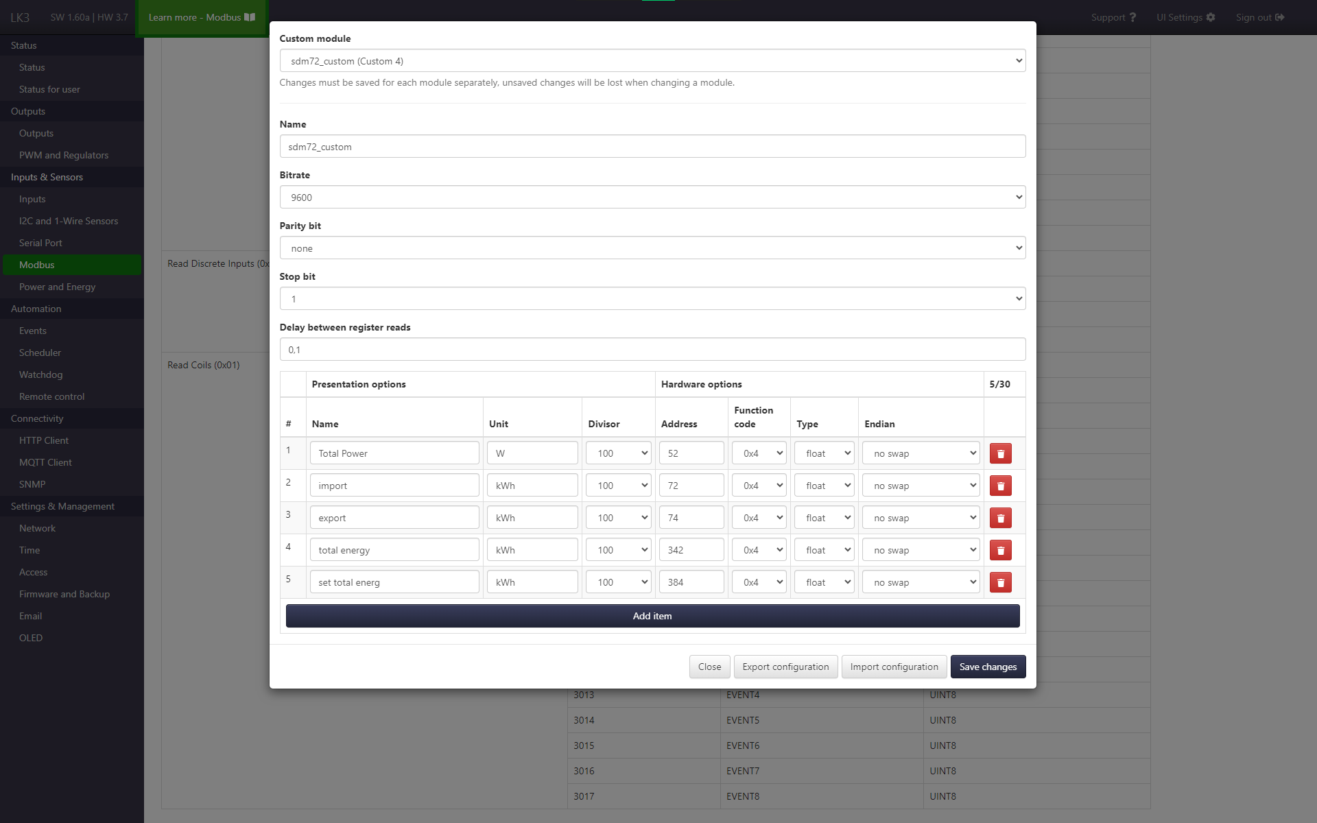
If you want to use a module for which there is no built-in support, you can configure it as a custom device. This involves providing communication parameters and register definitions. This configuration can be used for one or multiple slots. Five different configurations can be saved (starting with HW 3.5+ SW 1.57, previously 3).
Starting with HW 3.5+ SW 1.60a, the configuration panel is immediately accessible via the Configure custom modules button. In previous versions, to open the configuration panel, select one of the options marked (custom) in the Module field and then open the form with the Configure custom module button (this can be done on any slot).
In the form, enter your own name, communication data (bitrate, parity bit, stop bit, delay between register reads (in s)) and define the list of readings, giving each name, unit, divisor, register address, function code, type and endian (from HW 3.5+ SW 1.57). After completing the configuration, confirm with the Save changes button. Then the configuration can be selected on each of the three slots.
The configuration can be exported to a file by clicking the Export configuration button and loaded by clicking Import configuration (save changes after import). Sample configuration to be imported for SDM72D is available for download here.
More configuration files are available at our forum. However, please be aware that these configurations might have been contributed by other users, and as such, we cannot guarantee their accuracy or proper functioning. While we strive to curate and verify the content, we encourage you to exercise caution when using these configurations. Your feedback and experiences with these configurations are valuable to the community and can help ensure their reliability.
Readings mapping
In order to use readings from Modbus modules and additional 1-Wire sensors (e.g. SCD40) in other LK functions (such as HTTP client, MQTT client, OLED, VOLED, GSM Modem) apart from the Modbus or I2C and 1-Wire Sensors tab, you must configure mapping of readings to variables m1 - m30. On both of these pages there is a Configure Mapping button that opens a configuration form (shown in the image below). The reading is assigned to the m variable, and more precisely the reading position (this is important when changing Modbus modules, because the mapping to a specific slot number and reading number remains, so a slot without a selected module can be indicated).
From version HW 3.5+ SW 1.57, readings from additional 1-Wire sensors can be assigned to variables m1-m30.
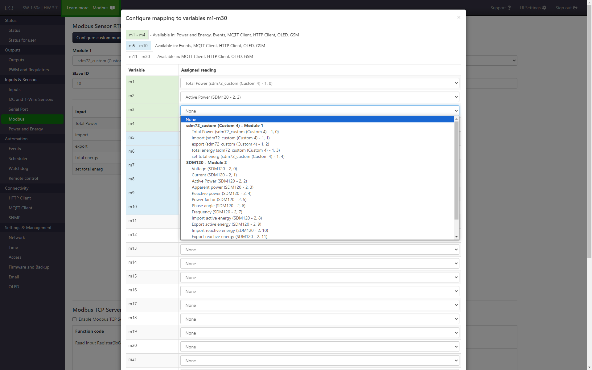
The variables m1 - m30 can be used later in the HTTP client, MQTT client, OLED, VOLED, GSM. The first 10 m1-m10 are available in Events too. The first 4 variables m1 - m4 are also available as an option I (power reading) and U (voltage reading) in Power and Energy tab.
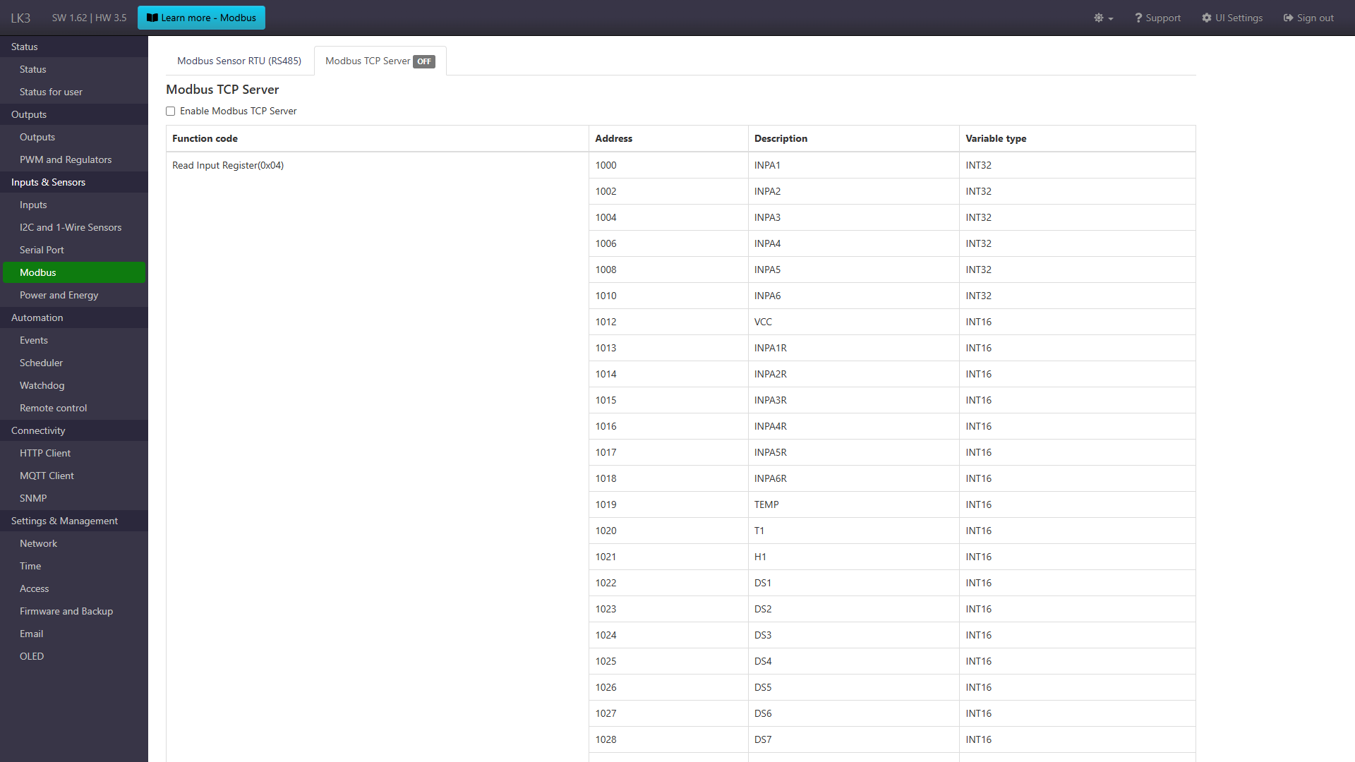
Modbus TCP Server
Form for enabling Modbus TCP Server and table with information about available data.