Introduction
The following description is intended to familiarize you with the configuration and basic use of GSM Controller v4.2.
First run
First, insert a nanoSIM card into the SIM slot in GSMv4.2, connect the power supply (voltage 5-55V).
Soon (up to 30 seconds) the green LED should blink 3 times per second. This means that the device has successfully connected to the network. You can then go to controller configuration.
Possible problems
If the LED flashes once every second, it means there is no network connection. Check the validity of the card.
If the LED is blinking once every 3 seconds, it means connected to the network, but no GPRS packet transmission. Check the APN settings with your card operator. By default, GSMv4.2 uses the following settings:
- APN: "internet"
- user: "" (not set)
- password: "" (not set)
If the operator settings are different, send an SMS to the card number in the GSM controller with the following text: 1234:gprsapn="<APN>","<user>","<password>", e.g. 1234:gprsapn="internet","","". After sending the command, wait several seconds and restart the controller (disconnect and reconnect the power or send the command 1234:restart).
Communication with the controller
There are three ways to send commands to the GSM v4.2 controller, which are described below. The command list is available here.
Serial port
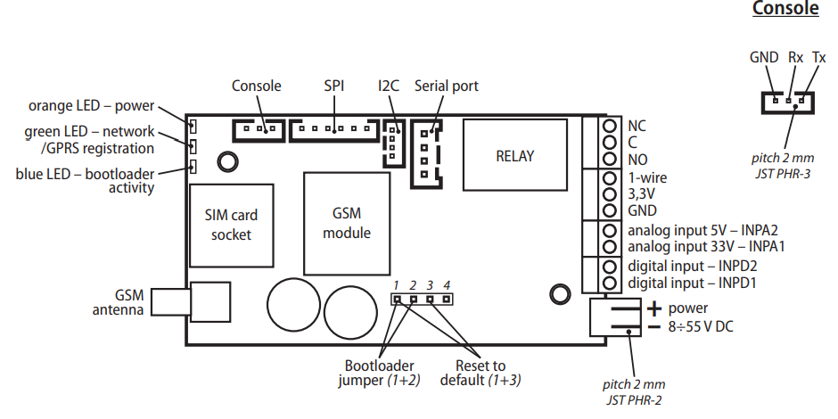
It requires the connection of the controller to the computer via a USB/TTL/UART/RS232 converter. The connector on the controller to which you need to connect is visible in the diagram below under the name Console (connection with the JST PHR-3 plug).
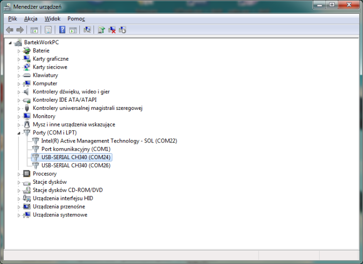
After connecting the computer with the GSM Controller, find the COM port address on which the Controller is available - in Windows you can check it in Device Manager (My Computer > Manage / Start > Device Manager). In this case it is COM24.
Any application that supports UART/Serial communication can be used to handle the connection. For example on Windows: PuTTy, ExtraPuTTy, Tera Term, minicom (Linux/OSX), screen (OSX). Personally, I like to use the miniterm tool included in the Python library pySerial.
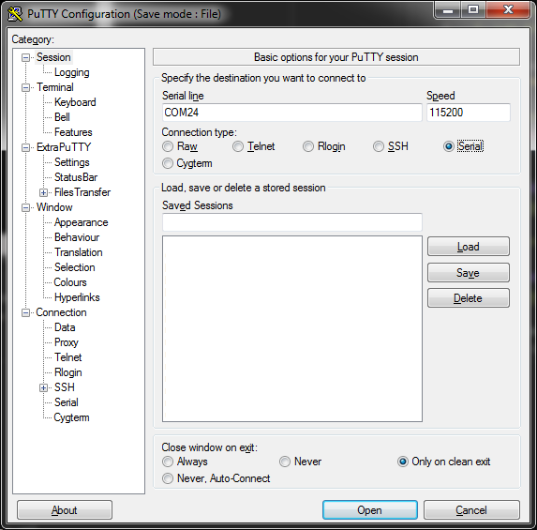
In the connection options, select a baudrate equal to 115200.
The access code must be entered before the first command (default is 1234). Otherwise, the controller will respond with message suggesting entering the code. You can then send commands as shown in the command list.
SMS
Commands can be sent to the phone number of the card inserted in the controller. Each command must be preceded by an access code and :, e.g. 1234:version?.
To change the access code, send the command: 1234:code=XXXX, where XXXX is the new four-digit access code.
In addition to the access code, it is possible to additionally secure access to the device by verifying the numbers that send the commands. To do this, first add your phone number to the list of trusted numbers with the command 1234:number=1:XXXXXXXXX. It is worth making sure that the number has been set correctly, with the command 1234:number?1 - the answer should contain the phone number previously set. After confirming that the number is on the list of trusted numbers, you can send the command 1234:authsms=1. From now on, GSMv4.2 will only accept commands from trusted numbers (see commands number, numread), on top of checking that the text of SMS starts with the access code.
For SMS communication with the controller, an important option is smsconfirm - it defines whether the controller will send back messages to commands (by default they are sent back).
MQTT
The GSM v4.2 controller supports communication via the MQTT protocol, which includes its full configuration, unlike the previous version v3.
Before sending commands, the controller must be connected to the MQTT server (see configuration description). Once connected, commands should be sent to topic prefix/cmd, and responses from the controller will be sent back to prefix/cmdr.
In the case of MQTT, the commands do not need to include an access code as the authentication is done in the MQTT protocol itself, e.g. version?.
MQTT client configuration
Service mqtt.ats.pl
GSM Controller v4.2 is prepared for cooperation with the mqtt.ats.pl server, thanks to which you can record readings from the device for later review, configure device and control it remotely via MQTT.
Instructions for connecting to the mqtt.ats.pl
After connecting to the server, the configuration of the GSM Controller v4.2 is much simpler than the previous version v3 - configuration via the website, without connecting the GSM Controller to the computer.
Another MQTT server
If you want to connect the GSM Controller to another server, you need to configure its MQTT client with the following commands that can be sent via the console or SMS. More information on each command by clicking on its name.
mqttconfigdone=1mqttserver=<SERVER ADDRESS>mqttport=<SERVER PORT>mqttuser=<USER NAME>mqttpass=<PASSWORD>tls=1(since SW 1.29)mqttid=<TOPIC PREFIX>mqttkeepalive=<KEEPALIVE PARAMETER>mqttselect=<LIST OF DATA INDEXES TO SEND>mqttsend=<INTERVAL OF DATA SEND>mqttread=<NUMBER OF READINGS IN THE MESSAGE>
Firmware update
The firmware update of the GSM Controller v4.2 is performed by means of the Serial/UART connection. For firmware upload, the XMODEM protocol is used, which is supported in the ExtraPuTTy or Tera Term application. The following description uses ExtraPuTTy.
In the program, select the connection type to Serial, enter the port address and speed 115200.
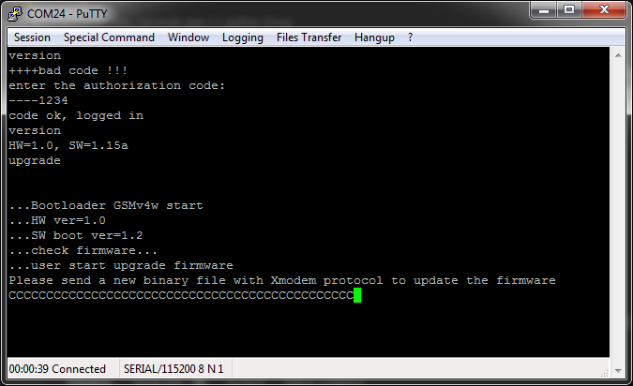
After opening the connection with the Open button, enter in the console (each command should be confirmed with Enter):
- access code (default 1234)
- version - to check the firmware version on the device
- upgrade - to start the update procedure
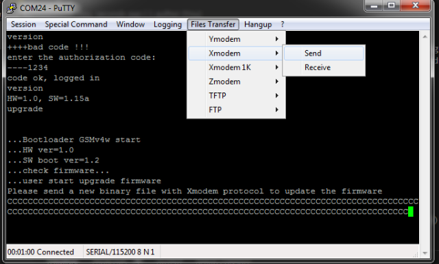
Start uploading the firmware file by clicking Files Transfer > Xmodem > Send and selecting the file location. Firmware to download here.
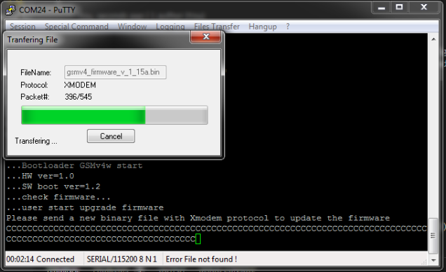
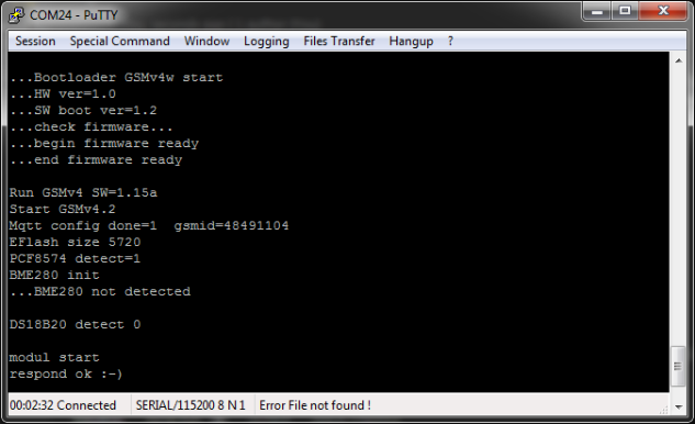
After the upload is completed, the GSM Controller will restart and display, among others, information about the firmware version. In some cases, it may be necessary to reconfigure the device (information about it usually in the firmware description).